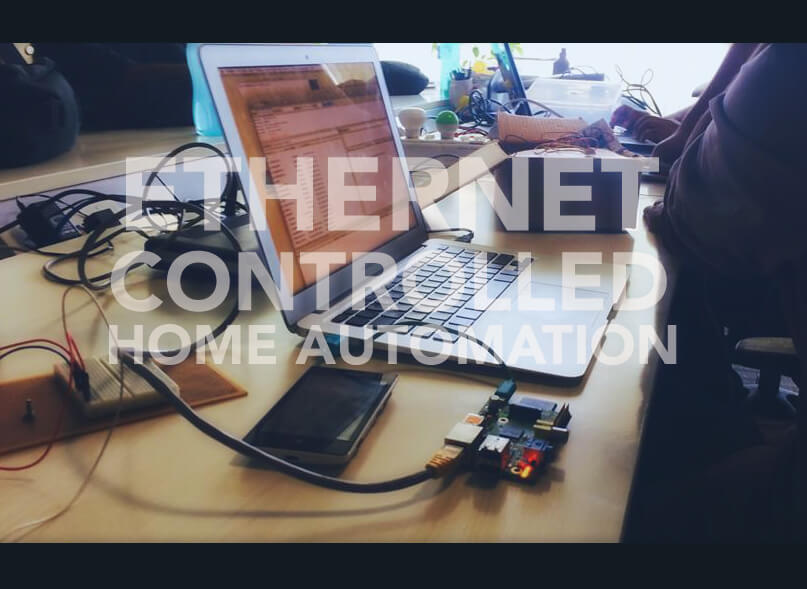


If you are short on money and cannot afford a Raspberry Pi for your Internet Of Things project you can use the Arduino with an ethernet shield to control the pins and read the values Follow this short tutorial to create a project to control a few LED’s with the GPIO pins and read Analog Sensor data from the Analog Pins. It takes only a couple of minutes to finish the project as long as your know how to use the Arduino IDE and know how to upload and edit the basic blink sketch.
The Hardware Needed :
- Arduino UNO
- Ethernet Shield
- Jumper Cables
Wiring :
- 4,5,6 – Digital Out/ LED A2 – Temperature Sensor LM35 A3 – LDR
The Arduino Sketch :
#include <Ethernet.h> // FOR THE ETHERNET LIBRARY
#include <SPI.h> //
#include <IRremote.h> // FOR SENDING IR COMMANDS
IRsend irsend; // SEDNDING IR CODES

// IR VALUES

unsigned int AC_ON1[60]={8450,4100,600,1450,650,400,600,450,600,450,600,1500,600,400,650,400,600,450,600,450,600,450,600,450,600,400,650,400,600,450,600,450,600,450,600,400,650,400,650,1450,600,1500,600,400,650,1450,600,450,600,450,600,450,550,1500,600,1500,600,1500,600};
unsigned int AC_OFF1[60]={8450,4050,600,1500,600,450,600,450,600,400,650,1450,600,450,600,450,600,400,650,1450,600,1500,600,450,600,400,650,400,600,450,600,450,600,450,600,450,600,400,650,400,600,450,600,450,600,1500,600,400,650,1450,600,450,600,450,600,400,650,1450,600};
unsigned int chUp1[36]={500,200,200,250,200,550,250,350,250,500,250,200,250,200,250,200,200,250,150,600,200,550,250,350,250,700,200,250,200,550,250,200,200,250,200};
unsigned int chDw1[36]={500,200,200,200,250,550,250,350,250,500,250,250,150,250,200,250,200,200,250,200,200,550,250,350,250,700,250,200,250,500,250,200,250,350,250};
unsigned int Source1[67]={4550,4500,600,1650,650,1600,650,1600,650,500,600,500,650,500,600,550,600,500,600,1650,650,1600,650,1600,650,500,600,500,650,500,600,550,600,500,650,1600,650,500,600,500,650,500,600,500,650,500,600,500,600,550,600,550,600,1650,600,1650,600,1650,600,1650,650,1600,600,1650,650,1600,650};

// LED STUFF

boolean a=0;// LED 1 STATUS
boolean b=0;// LED 2 STATUS
boolean c=0;// SWITCH CASE
boolean d=0;// LED 3 STATUS
float temp_val = 0; //  TEMPERATUERE VALUE
float ldr_val = 0; // LIGHT INTENSITY VALUE
boolean reading = false; //ETHERNET

// ETHERNET SETTINGS

 byte ip[] = { 192, 168, 1, 175 };
 byte gateway[] = { 192, 168, 1, 1 };
 byte subnet[] = { 255, 255, 255, 0 };
 byte mac[] = { 0xAD, 0xAE, 0xBD, 0xDF, 0xAE, 0xED };
 EthernetServer server = EthernetServer(80); //port 80


// IR REMOTE STUFF

void AC_ON()
{
   irsend.sendRaw(AC_ON1,60,38);
   delay(20);
  }

void AC_OFF()
{
   irsend.sendRaw(AC_OFF1,60,38);
   delay(20);
  }

void chUp()
{
  for(int i = 0; i < 5; i++) {
   irsend.sendRaw(chUp1,36,38);
   delay(20);
   }
  }

void chDw()
{
  for(int i = 0; i < 10; i++) {
   irsend.sendRaw(chDw1,36,38);
   delay(20);
   }

  }

void Source()
{
   irsend.sendRaw(Source1,67,38);
   delay(20);
   Serial.print("Source changed ");

  }

void Temp()
{

}

void Ldr()
{

}


void setup(){
  Serial.begin(9600);


  pinMode(4,OUTPUT); //LED 1
  pinMode(5,OUTPUT); //LED 2
  pinMode(6,OUTPUT); //LED 3
  analogReference(INTERNAL); // Setup the Reference Voltage as Internal


  Ethernet.begin(mac);
  Ethernet.begin(mac, ip, gateway, subnet); //for manual setup

  server.begin();
  Serial.println(Ethernet.localIP());

}

void loop(){

  // listen for incoming clients, and process qequest.
  checkForClient();

}

void checkForClient(){

  EthernetClient client = server.available();

  if (client) {

    // an http request ends with a blank line
    boolean currentLineIsBlank = true;
    boolean sentHeader = false;

    while (client.connected()) {
      if (client.available()) {

        if(!sentHeader){
          // send a standard http response header
          client.println("HTTP/1.1 200 OK");
          client.println("Content-Type: text/html");
          client.println();
          sentHeader = true;
        }

        char c = client.read();

        if(reading && c == ' ') reading = false;
        if(c == '?') reading = true; //found the ?, begin reading the info

        if(reading){
          Serial.print(c);

  switch (c) {
  // CONTROLLING THE AC

  case 'O':    // -O Turn On AC
    AC_ON();
    break;
  case 'F':    // - F Turn Off AC
    AC_OFF();
    break;
  case 'U':    // - U Channel Up
    chUp();
    break;
  case 'D':    // - D Channel Down
    chDw();
    break;

 // CONTROLLING THE LEDs

  case '1':    // LED 1 ON
    if(a==0){
    digitalWrite(4,HIGH);
    client.print("Light1 Turned On ");
    a=1;}
    break;
  case '2':    // LED 1 OFF
   if(a==1){
    digitalWrite(4,LOW);
    client.print("Light1 Turned Off ");
    a=0;}
    break;

  case '3':   // LED 2 ON
    if(b==0){
    digitalWrite(5,HIGH);
    client.print("Light2 Turned On ");
    b=1;}
    break;
  case '4':    // LED 2 OFF
  if(b==1){
    digitalWrite(5,LOW);
    client.print("Light2 Turned Off ");
    b=0;}
    break;


  case '5':    // LED 3 ON
    if(d==0){
    digitalWrite(6,HIGH);
    client.print("Light2 Turned On ");
    d=1;}
    break;
  case '6':    // LED 3 OFF
  if(d==1){
    digitalWrite(6,LOW);
    client.print("Light2 Turned Off ");
    d=0;}
    break;


  // STORE THE STATUS OF THE PINS


   case '7':    // POST VALUE OF LED 1
   client.print(a);
     break;

   case '8':    // POST VALUE OF LED 2

    client.print(b);
     break;

   case '9':   // POST VALUE OF LED 3

    client.print(d);
     break;


  case 'T':    // -T Print the temperature
   {
   int sensor_val = analogRead(2); // Read the raw sensor value and store it in the variable
  temp_val = sensor_val * 0.11; // The calculated value
  client.println(temp_val); // print the temperature value to serial monitor
   }
   break;


  case 'L':    // -L Light Intensity
    {
      ldr_val = analogRead(3);// Reads a 10-bit value corresponding to the voltage applied on analog input pin 3.
      client.println(ldr_val);//
    }  break;

           }
        }

        if (c == '\n' && currentLineIsBlank)  break;

        if (c == '\n') {
          currentLineIsBlank = true;
        }else if (c != '\r') {
          currentLineIsBlank = false;
        }

      }
    }

    delay(1); // give the web browser time to receive the data
    client.stop(); // close the connection:

  }

}
Usage
Change the Ethernet Settings according to your default gateway
You can add new cases in the switch statement for controlling more pins or adding new sensors. When an LED is turned On or Off the status is update in the value. This can be used to check the state of the led to make real time applications that are in sync with each other.
LED STATUS
http://ArduinoIpaddress/?7
The status of the led’s can be obained from here. If the LED is on you get 1 if it is off you get 0.
Sensor Details
Temperature Sensor
http://ArduinoIpaddress/?T
LDR Sensor
http://ArduinoIpaddress/?L